配置双向PIM与PIM-SM共存示例
组网需求
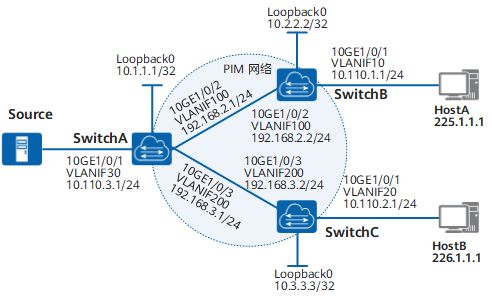
在如图4-30所示的网络中,HostA希望通过双向PIM协议接收组播组225.1.1.1的信息,HostB希望通过PIM-SM协议接收组播组226.1.1.1的信息。
图4-30 配置双向PIM与PIM-SM共存组网图
配置思路
在SwitchA上分别配置为双向PIM和PIM-SM服务的动态RP,并通过ACL规则指定动态RP服务的组播组范围,可以实现双向PIM与PIM-SM在同一网络中共存。具体配置思路如下:
- 配置各交换机的接口IP地址和单播路由协议。
- 在所有提供组播服务的交换机上使能组播路由。
- 在所有提供组播服务的交换机上使能双向PIM功能。
- 在组播交换机的所有接口上使能PIM-SM。
- 在与主机直连的交换机接口上使能IGMP。
- 配置动态RP。在SwitchA上分别配置为双向PIM服务和为PIM-SM服务的动态RP,并配置ACL过滤规则,分别匹配双向PIM和PIM-SM的RP服务的组播组范围。
操作步骤
配置各交换机的接口IP地址和单播路由协议。
按照图4-30配置各交换机接口的IP地址和掩码,配置各交换机间采用OSPF进行互连,确保网络中各交换机间能够在网络层互通,并且之间能够借助单播路由协议实现动态路由更新。
# 配置SwitchA的接口加入VLAN。SwitchB和SwitchC的配置与SwitchA相似,配置过程略。
system-view
[~HUAWEI] sysname SwitchA
[*HUAWEI] commit
[~SwitchA] vlan batch 30 100 200
[*SwitchA] interface 10ge 1/0/1
[*SwitchA-10GE1/0/1] port default vlan 30
[*SwitchA-10GE1/0/1] quit
[*SwitchA] interface 10ge 1/0/2
[*SwitchA-10GE1/0/2] port link-type trunk
[*SwitchA-10GE1/0/2] port trunk allow-pass vlan 100
[*SwitchA-10GE1/0/2] quit
[*SwitchA] interface 10ge 1/0/3
[*SwitchA-10GE1/0/3] port link-type trunk
[*SwitchA-10GE1/0/3] port trunk allow-pass vlan 200
[*SwitchA-10GE1/0/3] quit
[*SwitchA] commit
# 配置SwitchA上接口的IP地址。SwitchB和SwitchC的配置与SwitchA相似,配置过程略。
[~SwitchA] interface vlanif 30
[*SwitchA-Vlanif30] ip address 10.110.3.1 24
[*SwitchA-Vlanif30] quit
[*SwitchA] interface vlanif 100
[*SwitchA-Vlanif100] ip address 192.168.2.1 24
[*SwitchA-Vlanif100] quit
[*SwitchA] interface vlanif 200
[*SwitchA-Vlanif200] ip address 192.168.3.1 24
[*SwitchA-Vlanif200] quit
[*SwitchA] interface loopback0
[*SwitchA-LoopBack0] ip address 10.1.1.1 32
[*SwitchA-LoopBack0] quit
[*SwitchA] commit
# 配置SwitchA上的单播路由协议OSPF。SwitchB和SwitchC的配置与SwitchA相似,配置过程略。
[~SwitchA] router id 10.1.1.1
[*SwitchA] ospf
[*SwitchA-ospf-1] area 0
[*SwitchA-ospf-1-area-0.0.0.0] network 10.110.3.0 0.0.0.255
[*SwitchA-ospf-1-area-0.0.0.0] network 192.168.2.0 0.0.0.255
[*SwitchA-ospf-1-area-0.0.0.0] network 192.168.3.0 0.0.0.255
[*SwitchA-ospf-1-area-0.0.0.0] network 10.1.1.1 0.0.0.0
[*SwitchA-ospf-1-area-0.0.0.0] commit
[~SwitchA-ospf-1-area-0.0.0.0] quit
[~SwitchA-ospf-1] quit
在各交换机上使能组播功能和双向PIM功能。
# 使能SwitchA的组播功能和双向PIM功能。SwitchB和SwitchC的配置与SwitchA相似,配置过程略。
[~SwitchA] multicast routing-enable
[*SwitchA] pim
[*SwitchA-pim] bidir-pim
[*SwitchA-pim] commit
[~SwitchA-pim] quit
在各交换机接口上使能PIM-SM功能。
# 使能SwitchA的各接口PIM-SM功能。SwitchB和SwitchC的配置与SwitchA相似,配置过程略。
[~SwitchA] interface vlanif 30
[~SwitchA-Vlanif30] pim sm
[*SwitchA-Vlanif30] quit
[*SwitchA] interface vlanif 100
[*SwitchA-Vlanif100] pim sm
[*SwitchA-Vlanif100] quit
[*SwitchA] interface vlanif 200
[*SwitchA-Vlanif200] pim sm
[*SwitchA-Vlanif200] quit
[*SwitchA] interface loopback0
[*SwitchA-LoopBack0] pim sm
[*SwitchA-LoopBack0] quit
[*SwitchA] commit
在连接用户主机的接口上使能IGMP。
# 配置SwitchB。
[~SwitchB] interface vlanif 10
[~SwitchB-Vlanif10] igmp enable
[*SwitchB-Vlanif10] commit
[~SwitchB-Vlanif10] quit
# 配置SwitchC。
[~SwitchC] interface vlanif 20
[~SwitchC-Vlanif20] igmp enable
[*SwitchC-Vlanif20] commit
[~SwitchC-Vlanif20] quit
配置动态RP。
# 在SwitchA上配置不同的C-RP接口为不同的PIM协议服务。
[~SwitchA] acl number 2000
[*SwitchA-acl4-basic-2000] rule permit source 225.1.1.0 0.0.0.255
[*SwitchA-acl4-basic-2000] quit
[*SwitchA] acl number 2001
[*SwitchA-acl4-basic-2001] rule permit source 226.1.1.0 0.0.0.255
[*SwitchA-acl4-basic-2001] quit
[*SwitchA] pim
[*SwitchA-pim] c-bsr vlanif30
[*SwitchA-pim] c-rp loopback0 group-policy 2000 bidir
[*SwitchA-pim] c-rp vlanif30 group-policy 2001
[*SwitchA-pim] commit
[~SwitchA-pim] quit
验证配置结果。
# 使用display pim routing-table命令可以查看交换机上的PIM路由表。组播源(10.110.3.100/24)向组播组(225.1.1.1/24)、(226.1.1.1/24)发送信息,HostA加入了组播组(225.1.1.1/24),HostB加入了组播组(226.1.1.1/24)。例如SwitchA和SwitchB上的PIM路由表信息如下:
[~SwitchA] display pim routing-table
VPN-Instance: public net
Total 2 (*, G) entries; 1 (S, G) entry

(*, 226.1.1.1)
    RP: 10.110.3.1 (local)
    Protocol: pim-sm, Flag: WC
    UpTime: 03:05:41
    Upstream interface: Register
        Upstream neighbor: NULL
        RPF prime neighbor: NULL
    Downstream interface(s) information:
    Total number of downstreams: 1
       1: Vlanif200
            Protocol: pim-sm, UpTime: 03:05:41, Expires: 00:02:50

(10.110.3.100, 226.1.1.1)
    RP: 10.110.3.1 (local)
    Protocol: pim-sm, Flag: SPT LOC ACT
    UpTime: 00:06:27
    Upstream interface: Vlanif30
        Upstream neighbor: NULL
        RPF prime neighbor: NULL
    Downstream interface(s) information:
    Total number of downstreams: 1
       1: Vlanif200
            Protocol: pim-sm, UpTime: 00:06:27, Expires: 00:03:04

(*, 225.1.1.1)
    RP: 10.1.1.1 (local)
    Protocol: bidir-pim, Flag: WC ACT
    UpTime: 03:00:42
    Rpf interface: LoopBack0
        Upstream neighbor: NULL
    Downstream interface(s) information:
    Total number of downstreams: 2
       1: Vlanif100
            Protocol: bidir-pim, UpTime: 03:00:42, Expires: 00:02:48
       2: LoopBack0(RPF)
            Protocol: bidir-pim, UpTime: 03:00:42, Expires: -
[~SwitchB] display pim routing-table VPN-Instance: public net Total 1 (*, G) entry; 0 (S, G) entry (*, 225.1.1.1) RP: 10.1.1.1 Protocol: bidir-pim, Flag: WC ACT UpTime: 00:01:08 Rpf interface: Vlanif100 Upstream neighbor: 192.168.2.1 Downstream interface(s) information: Total number of downstreams: 2 1: Vlanif10 Protocol: igmp, UpTime: 00:01:07, Expires: - 2: Vlanif100(RPF) Protocol: bidir-pim, UpTime: 00:01:08, Expires: -由显示信息可以看出,HostA通过双向PIM协议接收到了组播组225.1.1.1的信息、HostB通过PIM-SM协议接收到了组播组226.1.1.1的信息。
配置文件
SwitchA的配置文件
#
sysname SwitchA
#
vlan batch 30 100 200
#
router id 10.1.1.1
#
multicast routing-enable
#
acl number 2000
rule 5 permit source 225.1.1.0 0.0.0.255
#
acl number 2001
rule 5 permit source 226.1.1.0 0.0.0.255
#
interface Vlanif30
ip address 10.110.3.1 255.255.255.0
pim sm
#
interface Vlanif100
ip address 192.168.2.1 255.255.255.0
pim sm
#
interface Vlanif200
ip address 192.168.3.1 255.255.255.0
pim sm
#
interface 10GE1/0/1
port default vlan 30
#
interface 10GE1/0/2
port link-type trunk
port trunk allow-pass vlan 100
#
interface 10GE1/0/3
port link-type trunk
port trunk allow-pass vlan 200
#
interface LoopBack0
ip address 10.1.1.1 255.255.255.255
pim sm
#
ospf 1
area 0.0.0.0
network 10.1.1.1 0.0.0.0
network 10.110.3.0 0.0.0.255
network 192.168.2.0 0.0.0.255
network 192.168.3.0 0.0.0.255
#
pim
c-bsr Vlanif30
bidir-pim
c-rp Vlanif30 group-policy 2001
c-rp LoopBack0 group-policy 2000 bidir
#
return
SwitchB的配置文件
#
sysname SwitchB
#
vlan batch 10 100
#
router id 10.2.2.2
#
multicast routing-enable
#
interface Vlanif10
ip address 10.110.1.1 255.255.255.0
pim sm
igmp enable
#
interface Vlanif100
ip address 192.168.2.2 255.255.255.0
pim sm
#
interface 10GE1/0/1
port default vlan 10
#
interface 10GE1/0/2
port link-type trunk
port trunk allow-pass vlan 100
#
interface LoopBack0
ip address 10.2.2.2 255.255.255.255
pim sm
#
ospf 1
area 0.0.0.0
network 10.2.2.2 0.0.0.0
network 10.110.1.0 0.0.0.255
network 192.168.2.0 0.0.0.255
#
pim
bidir-pim
#
return
SwitchC的配置文件
#
sysname SwitchC
#
vlan batch 20 200
#
router id 10.3.3.3
#
multicast routing-enable
#
interface Vlanif20
ip address 10.110.2.1 255.255.255.0
pim sm
igmp enable
#
interface Vlanif200
ip address 192.168.3.2 255.255.255.0
pim sm
#
interface 10GE1/0/1
port default vlan 20
#
interface 10GE1/0/3
port link-type trunk
port trunk allow-pass vlan 200
#
interface LoopBack0
ip address 10.3.3.3 255.255.255.255
pim sm
#
ospf 1
area 0.0.0.0
network 10.3.3.3 0.0.0.0
network 10.110.2.0 0.0.0.255
network 192.168.3.0 0.0.0.255
#
pim
bidir-pim
#
return